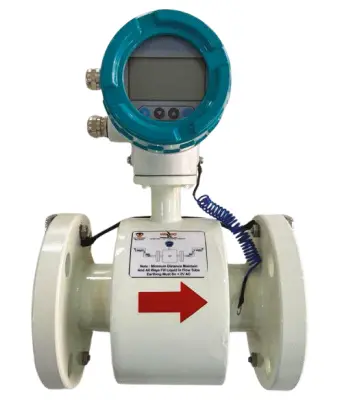
Electromagnetic Flow Meter
Wagad Electromagnetic Flow Meters are known by many names, including Magmeter, Magnetic Flow Meter, volumetric flow meter. Electromagnetic flow Meters measure the flow of conductive liquids in a pipe using electromagnetic induction. The flow meter works on Faraday’s law of electromagnetic induction. The meter measures the volumetric flow of water and displays it on a display unit. The basic requirement for the meter to work is the minimum electrical conductivity of water to be more than 5 micro Siemens/cm
A magnetic field is created around the Electromagnetic Flowmeter’s sensor, and as the liquid flows through the pipe, it distributes the magnetic field. This distribution is used to calculate the flow rate. Electromagnetic flow meters are used in a wide variety of industries, including water and wastewater treatment, chemical processing, and processing.
| APPLICATION |
| Sewage Treatment Plant |
| Food/Beverage Industries |
| Paper and Pulp Industries |
| Pharmaceutical all meaning |
| Water and Waste Water Management |
| Water Heating Boilers |
| ETP Plant |
| Power Industries |
| Mining & Cement Industries |
| Fertilizer Industries |
TECHNICAL DATA | |
| Diameter | PTFE: DN2.5-DN1000 |
| Rubber: DN50-DN3000 | |
| Flow Direction | Positive; Negative |
| Repeatability Error | 0.10% |
| Accuracy | +0.5% of rate; +0.2% of rate |
| Medium Temperature | Rubber liner: -20…+60°C |
| PTFE liner: -20…+120 °C | |
| PFA: -20…+180°C | |
| Velocity | 0.3-10m/s |
| Ambient Temperature | -20…+60 °C |
| Relative Humidity | 5%~95% |
| Power Consumption | <20W |
| Protection | IP 65; IP 68 (Remote Type) |

Configuration Function Parameters
- Configuration : 4 Tactile Membrane Keys for Data Configuration
- Flow Totalizer Reset : Totalizer Reset Facility by Password Protection
- Unit : Gallon, Liter, M3, Cubic Feet (User Configurable)
- Low Cut-Off : User Configurable
- Flow Direction Flow : Soft error Selection or Forward/Reverse Flow Direction
- Indication Damping : Reverse/Forward Flow Indication with Sign Indication
- Time : User Configurable
Electronics Parameters
- Flowrate: 5 Digit and Auto Adjust With Line Size
- Flow Totalizer : 10-digit Totalizer Value
- Real-Time Clock: Available
- Bar graph: Corresponds to 0-100% Flow rate
- Tag Id: User Configure Id (Numeric)
- Velocity: 5 Digit Velocity 0.000 M/s to 10.000 M/s
Alarm Indication And Detection
- Flow Detection: Empty Pipe Detection
- Flow Indication: Forward /Reverse
- Alarm Indication: Flow Alarm, Batch, Communication Status
Sensor Description (Mechanical Parts)
- Lining Material: PTFE
- Electrode Material: SS316 (Default), Hastelloy C, Tantalum, Titanium
- Measuring Tube Material: SS304 (Default), SS316
- Coil Housing: SS304 (Default)
- End Connection: Flange, Tri Clover, SMS Connection
- Protection Class: IP65 (Standard), IP68 (Optional)
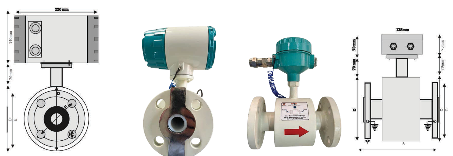
| DIMENSIONS | ||||||||
| (mm) | (inch) | Face To Face distance | Height | Flange Diameter | Pitch Circle Diameter (PCD) | Dia. of Hole | Thickness | Number of Holes |
| A | D | E | F | H | I | |||
| 15 | ½” | 200 | 117 | 88.9 | 60.4 | 15.7 | 11.2 | 4 |
| 20 | ¾” | 200 | 126 | 98.6 | 698.5 | 15.7 | 12.7 | 4 |
| 25 | 1” | 200 | 136 | 108.0 | 79.2 | 15.7 | 14.2 | 4 |
| 32 | 1 ¼” | 200 | 145 | 117.3 | 88.9 | 15.7 | 15.7 | 4 |
| 40 | 1 ½” | 200 | 155 | 127.0 | 98.6 | 15.7 | 17.5 | 4 |
| 50 | 2” | 200 | 180 | 152.4 | 120.7 | 19.1 | 19.1 | 4 |
| 65 | 2 ½” | 200 | 206 | 177.8 | 139.7 | 19.1 | 22.4 | 4 |
| 80 | 3” | 200 | 218 | 190.5 | 152.4 | 19.1 | 23.9 | 4 |
| 100 | 4” | 250 | 258 | 228.6 | 190.5 | 19.1 | 23.9 | 8 |
| 125 | 5” | 250 | 282 | 254.0 | 215.9 | 22.4 | 23.9 | 8 |
| 150 | 6” | 300 | 307 | 279.4 | 241.3 | 22.4 | 25.4 | 8 |
| 200 | 8” | 350 | 372 | 342.9 | 298.5 | 22.4 | 28.4 | 8 |
| 250 | 10” | 400 | 434 | 406.4 | 362.0 | 25.4 | 30.2 | 12 |
| 300 | 12” | 450 | 511 | 482.6 | 431.8 | 25.4 | 31.8 | 12 |
| 350 | 14” | 530* | 570* | 533.4 | 476.3 | 28.4 | 35.1 | 12 |
| 400 | 16” | 610* | 630* | 596.9 | 539.8 | 28.4 | 36.6 | 16 |
| 450 | 18” | 660* | 670* | 635.0 | 577.9 | 31.8 | 39.6 | 16 |
| 500 | 20” | 750* | 740* | 698.5 | 635.0 | 31.8 | 42.9 | 20 |
| Flow Rate Characteristics Values | ||
| Nominal Diameter | Recommended Flow Rate Min./ Max. Full Scale Value | |
| (mm) | (Inch) | (Velocity 0.3 to 10 m/s) |
| 15 | 0.5″ | 06 – 120.00 LPM |
| 20 | 3/4″ | 10 – 200.00 LPM |
| 25 | 1″ | 10 – 300.00 LPM |
| 32 | 1 1/4″ | 15 – 500.00 LPM |
| 40 | 1.5 | 25 – 700.00 LPM |
| 50 | 2″ | 35 – 1100.0 LPM |
| 65 | 2.5″ | 60 – 2000.0 LPM |
| 80 | 3″ | 4 – 150.00 m3/HR |
| 100 | 4″ | 8 – 270.00 m3/Hr |
| 125 | 5″ | 12 – 300.00 m3/Hr |
| 150 | 6″ | 20 – 600.00 m3/Hr |
| 200 | 8″ | 35 – 1100.0 m3/Hr |
| 250 | 10″ | 55 – 1700.0 m3/Hr |
| 300 | 12″ | 110 – 3300.0 m3/Hr |
| 350 | 14″ | 140 – 4200.0 m3/Hr |
| 400 | 16″ | 180 – 5400.0 m3/Hr |
| 450 | 18″ | 220 – 6600.0 m3/Hr |
| 500 | 20″ | 300 – 9600.0 m3/Hr |


